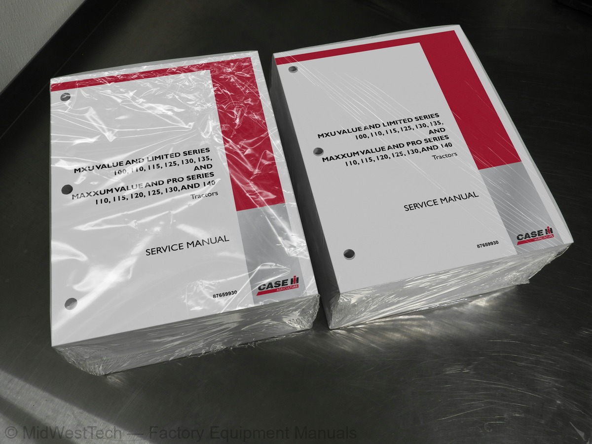
Case MXU Value Limited, Pro 110, 115, 120, 125, 130, 140 Tractor Service Manual
4,490 pages · Publication 87659930
Added to your cart. View cart
What's inside
From the manual's own table of contents: 14 sections, 264 entries. See sample pages (PDF, 723 KB)
SECTION 10 -- ENGINE171 topics
- Specifications
- Tightening Torques
- Special Tools
- Description of Operation
- Cooling
- Lubrication
- Lubrication System Components
- Engine Overhaul
- Introduction
- Removal
- Disassembly
- Fuel System/Preparing Engine to Mount on Rotating Stand
- Fuel Rail
- Cylinder Head
- Crankcase -- External Components
- Crank Shaft Seals
- Sump
- Rotating Counter Weights
- Crankshaft
- Camshaft
- Bushings
- Assembly
- Installing the Tappets – Camshaft
- Main Bearing Assembly
- Crankshaft Assembly
- Main Bearing Cap Assembly
- Connecting Rod and Piston Assembly
- Timing
- Crankshaft Seals and Covers
- Flywheel
- Oil Filter/Cooler
- Cylinder Head/Fuel System
- Completing the Engine
- Checks, Dimensions and Repairs
- Cylinder Block
- Cylinder Head Mating Surface Check
- Tappets
- Crankshaft, Bearings
- Main Journal Assembly Clearance
- Crankshaft Thrust ring Clearance Check
- Timing System
- Checking Cam Lift and Pin Alignment
- Pistons/Connecting Rods
- Measuring the Piston Diameter
- Piston Pins
- Conditions for Correct Pin--Piston Coupling
- Piston Rings
- Connecting Rods
- Checking Connecting Rods
- Checking Twisting
- Checking Bending
- Connecting Rod – Piston Assembly
- Fitting Piston Rings
- Connecting Rod Pin Assembly Clearance
- Checking Piston Protrusion
- Valve Disassembly
- Cylinder Head Hydraulic Seal Check
- Valve Dimensions
- Decarbonizing, Checking and Grinding Valves
- and Valve Centring
- Valve Guides
- Regrinding – Replacing Valve Seats
- Valve Springs
- Valve Installation
- Installing the Cylinder Head
- Checking and Adjusting Tappet Clearance
- Fuel Supply Gear Pump
- Normal Operating Condition
- Condition of Overpressure at Outlet
- Bleed Conditions
- High--Pressure Pump CP3
- High--Pressure Pump Internal Structure
- Operating Principle
- Operation
- Rail (Pressure Accumulator)
- Pressure Relief Valve
- Electro--Injector
- InjectionStart
- Injection End
- Fuel Return Pressure Limiter
- Overhaul
- Engine
- Checks, Repairs, Dimensions and Adjustments
- Camshaft Timing Operations
- Fitting the Cylinder Head
- Repairs -- Cylinder Block
- Checks and Measurements
- Main and Connecting Rod Journal Dimensions
- Connecting Rod--Piston Assembly
- Valves
- Valve Seats
- Rocker Arm–Spindle
- Adjusting Tappet Clearance
- High-Pressure Pump CP3
- Mechanical Grid Heater Operation
- Preparing Engine for Installation on Rotary Stand
- Thermostat Housing
- Turbocharger
- Fuel System
- Crankshaft Seals
- Fitting the Oil Nozzles
- Fitting the Connecting Rod Half Bearings
- Fitting the Piston -- Connecting Rod Assemblies in the Cylinder Liners
- Fitting the Connecting Rod Caps
- Fitting the Timing Gear Casing
- Fitting the Coolant Pump
- Fitting the Oil Pump
- Fitting the Oil Sump Seal
- Fitting the Counterweights
- Counterweight Timing Operations
- Fitting the Oil Sump
- Fitting the Flywheel
- Fitting the Oil Filter Mounting
- Fitting the Alternator
- Fitting the Cylinder Heads
- Fitting the Rocker Arm Assembly
- Fitting the Injectors
- Fitting the Tappet Covers
- Fitting the Exhaust Manifold
- Fitting the Thermostat
- Fitting the Fan Pulley Mounting
- Fitting the Alternator Belt
- Fitting the Intake Manifold
- Fitting the Priming Pump
- Fitting the Fuel Pipes
- Fitting the Fuel Filter
- Fitting the Turbo--Blower
- Cylinders
- Piston/Connecting Rods
- Connecting Rod Data
- Valve Data
- Assembling the Cylinder Head
- Bosch Rotary Fuel Injection Pump
- Manifold Pressure Compensator (LDA)
- Electrical Cold-start Accelerator (KKSB)
- Injection Pump Removal
- Injection Pump Installation
- Checking Injection Pump Timing
- Final Checks
- Description and Operation
- Mechanical Fuel Injected Engines
- Electronic Fuel Injected Engines
- Troubleshooting
- Cooling System Drain
- Tractors with Cab Heater
- Tractors Less Cab Heater
- All Tractors
- Cooling System Refill
- Radiator Removal
- Radiator Installation
- Radiator Inspection and Repair
- Thermostat
- Mechanical Fuel Injection Engines
- Thermostat Inspection
- Coolant Temperature Sensor
- Electronic Fuel Injection Engines
- Viscous Fan
- Installation
- Fan Blade Removal
- Fan Blade Installation
- Fan Belt
- Belt Tensioner
- Inspection and Repair
- Coolant Pump
- Fuel Tank
- Delphi Rotary Fuel Injection Pump
- Checking Injection Pump Static Timing
- Injection Pump Static Timing -- Adjustment
- Setting Pump Timing on an Untimed Pump (After Pump Removal without Locking)
- General specifications
- Cylinder Mechanical Engine -- F4CE0484B*D / F4CE9484B*J600
SECTION 35 -- HYDRAULIC SYSTEMS62 topics
- Principal of Draft Control
- Hydraulic Lift Assembly and Control Valve
- Hydraulic Pump
- Electronic Draft Control (EDC) Processor
- Load Sensing Pins
- Operator Controls
- Rear Fender Lift Lower Switches
- Operation of Draft Control
- Low Sensitivity Setting
- High Sensitivity Setting
- Hydraulic Operation of Lift Control Valve
- Flow Control Spool
- Raise Spool
- Raise Solenoid
- Load Check Valve
- Lift Cylinder Relief Valve
- Lower Solenoid
- Lowering Metering Valve
- Sectional Views
- Electronic Draft Control
- Neutral
- Raising
- Lowering
- Calibrations
- Error Codes
- Electronic Draft Control Valve
- Load Sensing Pin
- Remote Control Valves Not Working -- Electro--Hydraulic Remote Valves
- Fault Code Listing
- Control Levers
- Isolator Switch
- Manual and Programmable Lever Operation
- Manual Operation
- Timed Program Operation
- Programing a Double Acting Service
- Programing a Single Acting Service
- Replaying a Timed Program
- Deleting Programs
- Relieving System Pressure
- Quick Couplers
- Connecting Single-Acting Cylinders
- Connecting Double-Acting Cylinders
- Operating Continuous Flow Hydraulic Equipment
- Hydraulic Lift Simultaneously
- Bleeding Remote Cylinders
- Valve Description
- Solenoid Control Unit -- PCC Valve
- Load Hold Check Valve
- Lock Valve
- Control Valve Spool
- Spool Centering Spring
- Re--Calibrating Electronic Remote Valve Levers
- Oil Flow in Neutral
- Oil Flow in Raising (Cylinder Extend)
- Oil Flow in Lowering (Cylinder Retract)
- Oil Flow in Float
- Operation of Two or More Control Valves Simultaneously
- Electro Hydraulic Remote Valve Components
- Ehr Valve Number Programing
- Remote Valve
- Complete Valve Stack
- Configurable Detent Control
SECTION 55 -- ELECTRICAL SYSTEM17 topics
- Wiring Diagrams
- Circuit Descriptions (All Models)
- How to Use the Linear Wiring Diagrams
- Symbols
- Component Identification and Wiring Diagram Location Key
- 16x16 Transmission, W/Cab, W/Electronic Engine
- 16x16 Transmission, W/Cab, W/Mechanical Engine
- 24x24 Transmission, W/Cab, W/Electronic Engine
- 24x24 Transmission, W/Cab, W/Mechanical Engine
- 16x16 Transmission, L/Cab, W/Electronic Engine
- 16x16 Transmission, L/Cab, W/Mechanical Engine
- 24x24 Transmission, L/Cab, W/Electronic Engine
- 24x24 Transmission, L/Cab, W/Mechanical Engine
- 12x12 Transmission, W/Cab, W/Mechanical Engine
- 12x12 Transmission, L/Cab, W/Mechanical Engine
- 16x16 Transmission, W/Cab, W/Electronic Engine, W/EHR’s
- Wire Identification Key
Inside this manual
Real pages from this service manual (4,490 pages). Open the sample pages (PDF, 722 KB)

- Specifications, page 389: SECTION 10 -- ENGINE -- CHAPTER 3
- Diagram, page 596: SECTION 21 -- TRANSMISSION SYSTEMS -- CHAPTER 1
- Troubleshooting, page 4,253: ERROR CODE 15008 -- CHANGE VALVE SOLENOID OPEN CIRCUIT OR SHORT TO GROUND
- Color page, page 1,396: SECTION 35 -- HYDRAULIC SYSTEMS -- CHAPTER 3
- Color page, page 1,692: SECTION 35 -- HYDRAULIC SYSTEMS -- CHAPTER 11
- Foldout diagram (color), page 1,298: SECTION 35 -- HYDRAULIC SYSTEMS -- CHAPTER 1
Other manuals for this machine
Save 10% on 2 manuals, 15% on 3 or more. Other manuals are listed below. Editions cover different serial number ranges: check the serial coverage and tick only the ones that match your machine.
Added to your cart. View cart
This is a service manual
Here's how it compares to the other manual types.
Service manual
Factory repair procedures and technical information such as specifications, troubleshooting, and wiring and hydraulic diagrams, for the models and systems the manual covers. See What's inside for its topics.
Operator's manual
Safe operation, controls, maintenance schedules, lubrication points, inspections, and basic checks. Repair procedures are in the service manual.
Parts manual
Illustrated diagrams with factory part numbers for identifying components and ordering parts. Repair procedures are in the service manual.
Engine service manuals are sometimes sold separately, since certain machine models were offered with more than one engine option.
What it's used for
Factory manual for in-house farm and construction shop use. Straightforward, complete, and easy to follow. It contains the OEM information dealership service departments and parts counters use to diagnose problems, identify components, and perform maintenance or repairs correctly.
Service shops and owner/operators who repair their own equipment
Identifying correct parts and seeing how assemblies come apart and go back together
Keeping equipment running with less downtime
Factory manual, 4,490 pages
Quantity one is the manual described above.
Fast free USA shipping
Ships in 1 business day.
60-day returns
Free if the mistake is ours. A manual ordered in error must come back unopened in its shrink-wrap; you pay return shipping and a 20% restocking fee applies. Return policy
Binder not included
Manuals over about 300 pages may need a standard 3-ring binder, which you can buy locally to keep the pages organized for shop use.
Other editions and similar models
Questions about model, serial number, engine coverage or contents? Contact us before purchasing and we'll help confirm it's the right manual. Please verify the manual type, machine model, serial number range and engine coverage before purchasing: manuals ordered in error carry a 20% restocking fee (return policy).