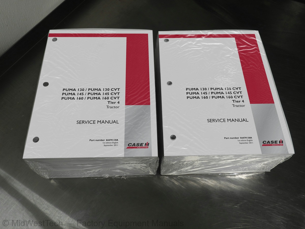
Case Puma 130, 145, 160 CVT Tier 4 Tractor Service Manual
2,449 pages · Publication 84479138A


Added to your cart. View cart
- Models
- Puma 130, 145, 160 CVT Tier 4
- Manual type
- Service Manual
- Pages
- 2,449
- Publication
- 84479138A
- Condition
- Brand new
What's inside
From the manual's own table of contents: 159 topics. See sample pages (PDF, 647 KB)
- Foreword
- Foreword Ecology and the Environment
- Safety rules
- Torque
- Basic instructions
- Conversion factors
- Consumables Lubrications and Coolants
- Capacities
- Variable displacement pump - General specification
- General specification
- Static description
- Hydraulic schema
- Exploded view
- Variable displacement pump - Dynamic description
- Test Using DATAR Equipment
- Variable displacement pump - Overhaul
- Variable displacement pump - Remove
- Overhaul
- Replace
- Dynamic description
- Disassemble
- Assemble
- Troubleshooting
- Sectional view
Show all 159 topics
- Remove
- Install
- CHARGING OR WELDING
- Component Diagram 00
- Component diagram 01
- Component diagram 02
- Component diagram 03
- Component diagram 05
- Component diagram 06
- Component diagram 07
- Component diagram 08
- Component diagram 09
- Component diagram 10
- Component diagram 11
- Component diagram 12
- Configure H-Menu Overview
- Electronic schema
- Instrument controller - Electronic schema
- Electronic park lock (EPL) controller - Electronic schema
- Universal controller - Electronic schema
- Armrest controller - Electronic schema
- Isobus interface controller (TECU) - Electronic schema
- Automatic Temperature Control (ATC) controller - Electronic schema
- Steering controller - Electronic schema
- Selective Catalytic Reduction (SCR) controller - Electronic schema
- Engine control module (ECM) - Electronic schema
- Navigation controller - Electronic schema
- Auxiliary (AUX) controller - Electronic schema
- Fault code index
- Instrument controller - H3 - Configurations and options
- Instrument controller - H4 - View software revision level
- Instrument controller - H5 - Switch operation test
- Instrument controller - H8 - Clear stored calibration information (EEPROM)
- Instrument controller - H9 - Voltmeter diagnostic
- Instrument controller - HB - Display stored fault codes
- Instrument controller - HC - Clear all stored fault codes
- Universal controller - H1 - Calibration procedures
- Universal controller - H2 - View stored calibration values
- Rocker assembly Shaft - Dimension
- Rocker assembly - Overview
- Cleaning
- Electrical test
- Low pressure - Connect
- Tighten - Sequence
- Control valve - Remove
- Control valve - Install
- Urea tank - Remove
- Urea tank - Install
- Supply Module - Remove
- Supply Module - Install
- Coolant control valve - Remove
- Coolant control valve - Install
- Power converter - Remove
- Power converter - Install
- SCR muffler - Remove
- SCR muffler - Install
- Sensing system NOx sensor - Remove
- Sensing system NOx sensor - Install
- Sensing system Temperature sensor - Remove Pre Catalyst
- Sensing system Temperature sensor - Install Pre Catalyst
- Sensing system Temperature sensor - Remove Post Catalyst
- Sensing system Temperature sensor - Install Post Catalyst
- Dosing module - Remove
- Dosing module - Install
- Filter - Remove Main Filter
- Filter - Install Main Filter
- Filter - Remove Inline Filter
- Filter - Install Inline Filter
- Sensing system Heated level sensor - Remove
- Sensing system Heated level sensor - Install
- Overview
- Drain fluid
- Filling
- Viscous drive - Remove
- Viscous drive - Install
- Remove Fan
- Install Fan
- Valve - Remove
- Valve - Install
- Adjust
- Pressure test
- Master clutch valve - Remove
- Master clutch valve - Disassemble
- Special tools
- Leakage test
- Disconnect
- Connect
- Dynamic description “Electronic park lock
- Functional diagram
- Exploded view (Transmission input)
- Exploded view (Transmission output)
- Exploded view (Solenoid valves, sensors, hydraulic lines)
- Overview (Safety valve)
- Overview (Solenoid valves)
- System pressure sensor - Overview (p1)
- Remove (Standard Axle)
- Install (Standard Axle)
- Remove (Suspended Axle)
- Install Suspended axle
- Disassemble (Class 3.5 Axle)
- Disassemble (Class 3+ Axle)
- Assemble (Class 3.5 Axle)
- Backlash (Class 3+ Axle)
- Clearance (Class 3+ Axle)
- Reducer, spur gear - Overhaul
- Shaft - Remove
- Shaft - Install
- Multi plate clutch - Overhaul
- Install (Suspended axle)
- Remove (All wheel drive shaft, transmission casing)
- Install (All wheel drive shaft, transmission casing)
- Install (drive shaft, transmission casing)
- Control valve - Torque
- Remove Steering Wheel - Standard
- Remove Steering Wheel with Turn Assist
- Install Steering Wheel - Standard
- Install Steering Wheel with Turn Assist
- Toe in adjust
- Static description Auto guidance system
- Dynamic description Autoguidance system
- Hydraulic schema Autoguidance system
- External view
- Testing
- Torque (Front support)
- Clearance (Front support)
- Magnetic clutch - Overview
- Temperature control potentiometer - Overview
- Overview (High pressure/low pressure switch)
- Low pressure switch - Overview
- Temperature sensor - Overview (Cabin Temperature)
- Temperature sensor - Overview (Outlet temperature)
- Exploded view Control Valve
- Remove Right Hand Link
- Install Right Hand Link
- Overhaul Right hand Link
Inside this manual
Real pages from this service manual (2,449 pages). Open the sample pages (PDF, 647 KB)

- Diagram, page 692: HYDRAULIC, PNEUMATIC, ELECTRICAL, ELECTRONIC SYSTEMS - ELECTRICAL POWER SYSTEM
- Troubleshooting, page 1,950: AXLES, BRAKES AND STEERING - FRONT AXLE
- Specifications, page 2,098: AXLES, BRAKES AND STEERING - STEERING Autoguidance
- Color page, page 1,520: Summing planetary gear
- Color page, page 106: Closed center mechanical remote valve
- Foldout diagram (color), page 1,534
Other manuals for this machine
Save 10% on 2 manuals, 15% on 3 or more. Other manuals for the 145 are listed below. Editions cover different serial number ranges: check the serial coverage and tick only the ones that match your machine.
Added to your cart. View cart
This is a service manual
Here's how it compares to the other manual types.
Service manual
Factory repair procedures and technical information such as specifications, troubleshooting, and wiring and hydraulic diagrams, for the models and systems the manual covers. See What's inside for its topics.
Operator's manual
Safe operation, controls, maintenance schedules, lubrication points, inspections, and basic checks. Repair procedures are in the service manual.
Parts manual
Illustrated diagrams with factory part numbers for identifying components and ordering parts. Repair procedures are in the service manual.
Engine service manuals are sometimes sold separately, since certain machine models were offered with more than one engine option.
What it's used for
Factory manual for in-house farm and construction shop use. Straightforward, complete, and easy to follow. It contains the OEM information dealership service departments and parts counters use to diagnose problems, identify components, and perform maintenance or repairs correctly.
Service shops and owner/operators who repair their own equipment
Identifying correct parts and seeing how assemblies come apart and go back together
Keeping equipment running with less downtime
Factory manual, 2,449 pages
Quantity one is the manual described above.
Fast free USA shipping
Ships in 1 business day.
60-day returns
Free if the mistake is ours. A manual ordered in error must come back unopened in its shrink-wrap; you pay return shipping and a 20% restocking fee applies. Return policy
Binder not included
Manuals over about 400 pages may need a standard 3-ring binder, which you can buy locally to keep the pages organized for shop use.
Other editions and similar models
Questions about model, serial number, engine coverage or contents? Contact us before purchasing and we'll help confirm it's the right manual. Please verify the manual type, machine model, serial number range and engine coverage before purchasing: manuals ordered in error carry a 20% restocking fee (return policy).