Terex Genie Z-45, Z-25, Z-25J Bi-Energy Power Articulated Boom Lift Service Manual
372 pages · Publication 106488
Added to your cart. View cart
- Models
- Genie Z-45, Z-25, Z-25J Bi-Energy Power
- Serial coverage
- from serial number 9996 to 23235
- Manual type
- Service Manual
- Pages
- 372
- Publication
- 106488
- Condition
- Brand new
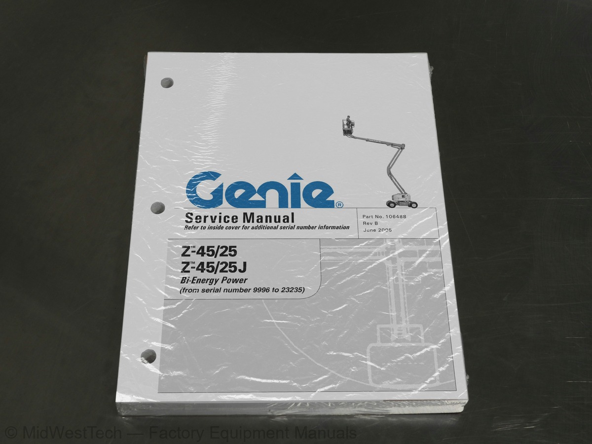
What's inside
From the manual's own table of contents: 121 topics. See sample pages (PDF, 609 KB)
- Important Information
- Serial Number Information
- Serial Number Legend
- General Safety Rules
- Machine Specifications
- Performance Specifications
- Hydraulic Specifications
- Manifold Component Specifications
- Machine Torque Specifications
- Kubota Z482-E Engine Specifications
- Generator
- Generator Torque Specifications
- Hydraulic Hose and Fitting Torque Specifications
- SAE and Metric Fasteners Torque Charts
- Introduction
- Pre-delivery Preparation
- Maintenance Inspection Report
- Perform Pre-operation Inspection
- Perform Function Tests
- Check the Generator Belts and Pulleys
- Perform 30 Day Service
- Perform Engine Maintenance
- Grease the Turntable Rotation Bearing and Rotate Gear
- A-10 Perform Engine Maintenance
Show all 121 topics
- Check the Radiator
- Check the Exhaust System
- Check the Batteries
- Inspect the Electrical Wiring
- Check the Lug Nut Torque (including the tires and wheels)
- Confirm the Proper Brake Configuration
- Check the Oil Level in the Drive Hubs
- Check and Adjust the Engine RPM
- Test the Ground Control Override
- B-10 Test the Platform Self-leveling
- B-11 Test the Engine Idle Select
- B-12 Test the Drive Brakes
- B-13 Test the Drive Speed - Stowed Position
- B-14 Test the Drive Speed - Raised or Extended Position
- B-15 Test the Alarm Package (if equipped)
- B-16 Test the Turntable Rotation Stop
- B-17 Check the Electrical Contactors
- B-18 Perform Hydraulic Oil Analysis
- B-19 Perform Engine Maintenance
- Grease the Platform Overload Mechanism (if equipped)
- Test the Platform Overload Mechanism (if equipped)
- Check the Primary Boom Wear Pads
- Check the Turntable Rotation Bearing Bolts
- Check the Free-wheel Configuration
- Replace the Drive Hub Oil
- Replace the Hydraulic Tank Return Filter
- Inspect for Turntable Bearing Wear
- Calibrate the Platform Overload System (if equipped)
- Test or Replace the Hydraulic Oil
- Grease the Steer Axle Wheel Bearings
- Controllers
- Platform Leveling Slave Cylinder
- Platform Rotator
- Jib Boom
- Jib Boom Lift Cylinder
- Cable Track
- Primary Boom
- Primary Boom Lift Cylinder
- Primary Boom Extension Cylinder
- Platform Leveling Master Cylinder
- Secondary Boom
- Secondary Boom Lift Cylinders
- Timing Adjustment
- RPM Adjustment
- Engine Drive Pulley
- Generator Pulley
- Generator Belts
- Generator Voltage Regulator
- Auxiliary Pump
- Function Pump
- Function Manifold Components (before serial number 17841)
- Function Manifold Components (from serial number 17841 to 20379)
- Function Manifold Components (from serial number 20380 to 22565)
- Function Manifold Components (from serial number 22566 to 23235)
- Valve Adjustments - Function Manifold
- Jib Boom / Platform Rotate Manifold Components
- Turntable Rotation Manifold Components
- Rotation Hydraulic Motor (before serial number 18367)
- Turntable Rotation Assembly (after serial number 18366)
- Motor Controller
- Fault Code Chart
- Electrical Symbols Legend
- Hydraulic Symbols Legend
- Power Cable Diagram (before serial number 16839)
- Power Cable Diagram (from serial number 16840 to 21179)
- Power Cable Diagram (from serial number 21180 to 22050)
- Power Cable Diagram (from serial number 22051 to 23235)
- Engine Panel Diagram (before serial number 13361)
- Engine Panel Diagram (from serial number 13361 to 14078)
- Engine Panel Diagram (from serial number 14079 to 14650)
- Engine Panel Diagram (from serial number 14651 to 16839)
- Engine Panel Diagram (from serial number 16840 to 17974)
- Engine Panel Diagram (from serial number 17975 to 21180)
- Engine Panel Diagram (from serial number 21181 to 22050)
- Engine Panel Diagram (from serial number 22051 to 23235)
- Electrical Schematic, Z-45/25 (before serial number 13361)
- Electrical Schematic, Z-45/25 (from serial number 13361 to 14078)
- Electrical Schematic, Z-45/25 (from serial number 14079 to 14650)
- Electrical Schematic, Z-45/25 (from serial number 14651 to 16839)
- Electrical Schematic, Z-45/25 (from serial number 16840 to 17974)
- Electrical Schematic, Z-45/25 (from serial number 17975 to 21180)
- Electrical Schematic, Z-45/25 (from serial number 21181 to 22050)
- Electrical Schematic, Z-45/25J (before serial number 13361)
- Electrical Schematic, Z-45/25J (from serial number 13361 to 14078)
- Electrical Schematic, Z-45/25J (from serial number 14079 to 14650)
- Electrical Schematic, Z-45/25J (from serial number 14651 to 16839)
- Electrical Schematic, Z-45/25J (from serial number 16840 to 17974)
- Electrical Schematic, Z-45/25J (from serial number 17975 to 21180)
- Electrical Schematic, Z-45/25J (from serial number 21181 to 22050)
- (before serial number 13361)
- ANSI and CSA Models (from serial number 22051 to 23235)
- ANSI and CSA Models (after serial number 22050)
- CE Models (from serial number 22051 to 23235)
- Hydraulic Schematic (before serial number 16962)
- Hydraulic Schematic (from serial number 16962 to 20379)
- Hydraulic Schematic (from serial number 20380 to 22565)
- Hydraulic Schematic (from serial number 22566 to 23235)
Inside this manual
Real pages from this service manual (372 pages). Open the sample pages (PDF, 609 KB)
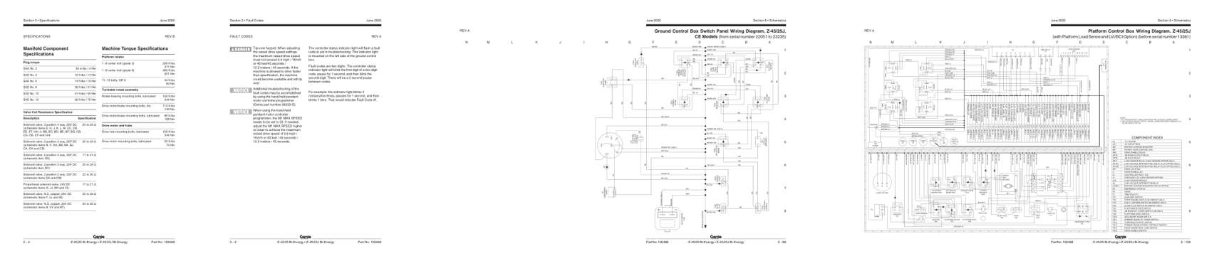
- Specifications, page 22: Section 2 • Specifications
- Troubleshooting, page 122: Section 5 • Fault Codes
- Diagram, page 297: Ground Control Box Switch Panel Wiring Diagram, Z-45/25J,
- Foldout diagram, page 333: Section 6 • Schematics
This is a service manual
Here's how it compares to the other manual types.
Service manual
Factory repair procedures and technical information such as specifications, troubleshooting, and wiring and hydraulic diagrams, for the models and systems the manual covers. See What's inside for its topics.
Operator's manual
Safe operation, controls, maintenance schedules, lubrication points, inspections, and basic checks. Repair procedures are in the service manual.
Parts manual
Illustrated diagrams with factory part numbers for identifying components and ordering parts. Repair procedures are in the service manual.
Engine service manuals are sometimes sold separately, since certain machine models were offered with more than one engine option.
What it's used for
Factory manual for in-house farm and construction shop use. Straightforward, complete, and easy to follow. It contains the OEM information dealership service departments and parts counters use to diagnose problems, identify components, and perform maintenance or repairs correctly.
Service shops and owner/operators who repair their own equipment
Identifying correct parts and seeing how assemblies come apart and go back together
Keeping equipment running with less downtime
Factory manual, 372 pages
Quantity one is the manual described above.
Fast free USA shipping
Ships in 1 business day.
60-day returns
Free if the mistake is ours. A manual ordered in error must come back unopened in its shrink-wrap; you pay return shipping and a 20% restocking fee applies. Return policy
Binder not included
Manuals over about 300 pages may need a standard 3-ring binder, which you can buy locally to keep the pages organized for shop use.
Other editions and similar models
Questions about model, serial number, engine coverage or contents? Contact us before purchasing and we'll help confirm it's the right manual. Please verify the manual type, machine model, serial number range and engine coverage before purchasing: manuals ordered in error carry a 20% restocking fee (return policy).